Solar Panel Series vs Parallel Wiring for Portable Power Stations
Quick Specification & Sizing Overview
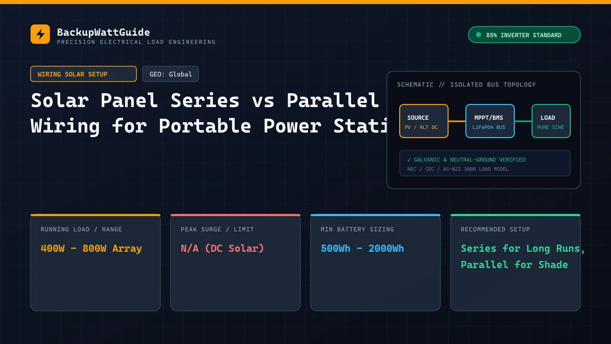
Connecting an external solar array to recharge a portable power station requires understanding your unit’s internal Maximum Power Point Tracking (MPPT) charge controller specifications.
Wiring panels incorrectly either severely throttles charging speed or, in worst-case scenarios, permanently destroys the MPPT input stage via high-voltage breakdown.
Electrical Characteristics Comparison
| Wiring Configuration | Voltage (V) Behavior | Amperage (A) Behavior | Conductor Gauge Requirement | Shading Sensitivity |
|---|---|---|---|---|
| Series (N panels) | V_total = V1 + V2 + … | I_total = I_string | Smaller gauge (e.g. 12 AWG / 14 AWG) | High (one shaded cell drops string) |
| Parallel (N panels) | V_total = V_panel | I_total = I1 + I2 + … | Thicker gauge (e.g. 10 AWG / 8 AWG) | Low (unshaded panels maintain output) |
1. When to Wire in Series
When you wire photovoltaic modules in series (connecting panel A positive to panel B negative), the voltages combine while the amperage remains that of a single panel:
Array Voltage = Voc1 + Voc2 + ... + VocN
Array Amperage = Isc (single string current)
Advantages of Series Wiring:
- Reduced Line Loss (I²R): Lower current allows longer cable runs without significant voltage drops.
- Earlier MPPT Lock-On: The MPPT controller starts charging earlier in the dawn and later into dusk because string voltage exceeds the internal battery voltage hurdle faster.
The Critical Cold-Weather Voltage Risk:
Solar panels are rated at Standard Test Conditions (STC) of 25°C (77°F). For every degree Celsius below 25°C, the panel voltage rises according to its Temperature Coefficient of Voc (typically -0.28% / °C).
If you connect two 24V Voc panels in series on a cold winter morning at -10°C (14°F):
Temperature Delta = -10°C - 25°C = -35°C
Voltage Multiplier = 1 + (-35 * -0.0028) = 1.098 (+9.8%)
Actual Cold Open-Circuit Voltage = 48V * 1.098 = 52.7V
If your power station has a strict 50V maximum DC limit, this 52.7V cold-weather voltage spike will trigger an immediate over-voltage trip or damage the input capacitors.
2. When to Wire in Parallel
When you connect panels in parallel using branch Y-connectors (positive to positive, negative to negative), voltage stays identical to one panel while amperage stacks:
Array Voltage = Single Panel Operating Voltage (Vmp)
Array Amperage = I1 + I2 + ... + IN
Advantages of Parallel Wiring:
- Safety Margin: Stays safely below the low-voltage cutoff threshold of budget power stations (e.g., 12V to 30V limits).
- Partial Shade Resilience: If partial tree shade falls over one panel, the unshaded parallel panel continues delivering full power.
Solar Recharge Time & Discharge Balance Estimator
# Frequently Asked Questions
Will wiring solar panels in series blow my power station's MPPT controller?
Yes, if the combined open-circuit voltage (Voc) exceeds the maximum DC voltage input rating of your power station. Voltage adds in series; exceeding the limit causes permanent hardware damage.
Why does cold weather increase solar panel voltage?
Silicon solar cells have a negative temperature coefficient. In freezing temperatures (-10°C to 0°C), Voc increases by 10% to 15% above standard test conditions (STC).
Lead Technical Electrical Editor
Peer-ReviewedPower Systems Analyst & Backup Power Specialist
All technical guides and electrical sizing benchmarks are calculated using standard Nameplate Full Load Amps (FLA), Locked Rotor Amps (LRA) surge models, and an empirically verified 85% Inverter Power Factor & Conversion Efficiency model.