How to Wire an Anderson Plug to XT60 for Charging Bluetti and EcoFlow
Quick Specification & Sizing Overview
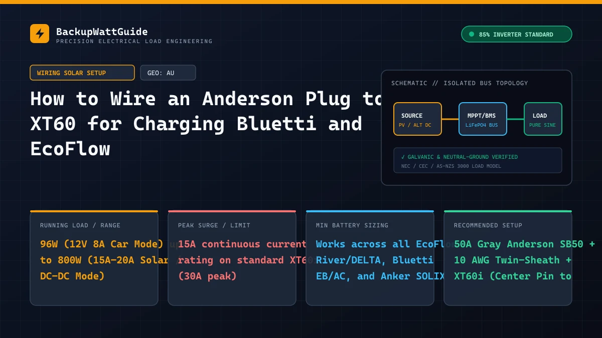
Across Australia, North America, and overland builds worldwide, the 50-Amp gray Anderson SB50 plug is the universal standard for 12V/24V canopy wiring, folding solar blankets, and dual-battery sockets. Meanwhile, EcoFlow, Anker SOLIX, and mid-size Bluetti portable power stations (such as the Bluetti AC180 and EcoFlow DELTA 2 / DELTA 2 Max / River 3) ditch bulky Anderson sockets on their faceplates in favor of compact yellow or orange XT60 / XT60i ports originally designed for high-current RC aircraft.
Buying a cheap $12 “Anderson to XT60” adapter off eBay or Amazon almost always leads to disappointment: you plug your 200W or 300W solar blanket into the power station, and the screen refuses to climb past 96W to 105W (capped at exactly 8.0 Amps). Worse, thin 16 AWG or 14 AWG wire hidden inside cheap molded adapters drops 1.5 Volts over a 3-metre run, heating the plug and tricking the power station’s MPPT controller into throttling input.
Here is the exact pinout specification, XT60 vs. XT60i sense-pin wiring diagram, and cable gauge table to build or buy an Anderson-to-XT60i lead that unlocks the full 15-Amp (up to 500W–800W) charging speed on your power station.
The secret behind the 8-Amp cap: Standard XT60 (2-pin) vs. XT60i (3-pin)
Look closely inside the solar/car charging port on an EcoFlow DELTA 2, DELTA 2 Max, DELTA Pro, or River series power station. Between the two main brass bullet pins sits a tiny flat gold contact tab in the very center.
That port is an Amass XT60i receptacle (i stands for Intelligent Signal Pin). Because EcoFlow uses that single port for both 12V Car Cigarette Socket Charging and High-Amperage Solar MPPT Charging, the power station needs a hardware way to know what kind of cord you just plugged in:
- Why Car Mode is capped at 8 Amps: A standard dashboard cigarette lighter socket in a Ute or SUV is wired with thin factory 18 AWG wire on a 10A fuse. If a power station pulled 15 Amps continuously from a cigarette socket, it would melt the dashboard plug.
- How the XT60i Center Sense Pin switches modes: The power station’s microcontroller sends a tiny 3.3V logic signal out onto that center third pin and checks whether it is left open, connected to Negative (
GND), or connected to Positive (+V).
Compare the three wiring states of the XT60i center pin below:
| Plug Type & Center Sense Pin Wiring | What the Power Station Detects | Maximum Amperage Allowed | Max Wattage at 13.5V (Vehicle/12V Solar) | Max Wattage at 40V (Series Solar Array) |
|---|---|---|---|---|
| Standard 2-Pin Yellow XT60 (No center pin at all) | Uncertain / Default Car Mode. Treats input as a fragile cigarette socket (unless overridden in app on select firmware). | 8.0 Amps (Sometimes 4A/6A/8A selectable in app) | ~108 Watts | ~320 Watts |
3-Pin XT60i with Center Pin Wired to Positive (+) | Explicit Car Cigar Lighter Cable. Locks the unit into vehicle protection mode. | 8.0 Amps (Hard-locked in hardware) | ~108 Watts | N/A |
3-Pin XT60i with Center Pin Wired to Negative (-) (Recommended for Solar & 50A Anderson) | High-Current Solar / MPPT Mode. Unlocks full MPPT controller current ceiling. | 15.0 Amps (Up to 15A–20A depending on model) | ~202 Watts | 500W to 800W+ (Up to MPPT voltage limit) |
What about Bluetti and Anker SOLIX? Bluetti models that use an XT60 input (such as the Bluetti AC60 or certain expansion cables) and Anker SOLIX C1000 / F1200 units using XT60 ports only connect the two main Positive and Negative barrels internally. However, an XT60i plug is 100% backward-compatible with standard 2-pin XT60 sockets. Building your Anderson cable with an XT60i plug (center pin tied to Negative) means that single cable works at full 15A speed on EcoFlow, Bluetti, and Anker SOLIX simultaneously!
Pinout & polarity verification: Anderson SB50 to XT60i
Reversing polarity on a 50A Anderson to XT60 cable will instantly trip the reverse-polarity MOSFET protection inside your MPPT controller—or, on older budget power stations without reverse-diode protection, blow the input board entirely (triggering a permanent fault that won’t clear even with our error code E01, E02, and E03 reset guide).
Always verify both ends visually before crimping or soldering:
+-------------------------------------------------------------------+
| 50A GRAY ANDERSON SB50 PLUG         AMASS XT60i FEMALE PLUG       |
| (Looking at Rear Wire Entry)        (Looking at Rear Solder Cups) |
|                                                                   |
|      [ + POSITIVE ]  ======== RED 10/12 AWG ========> ( + ) Flat  |
|                                                       [ i ] Sense |
|      [ - NEGATIVE ]  ======= BLACK 10/12 AWG =======> ( - ) Round |
|                                                         |         |
|                      (Bridge BLACK Negative to [i] Sense Pin!)    |
+-------------------------------------------------------------------+
1. Identifying Positive (+) and Negative (-) on the Anderson SB50 housing
Hold the gray 50-Amp Anderson SB50 plastic shell in your hand with the flat base facing down and look at the molded symbols stamped into the top of the plastic body:
- One wire barrel is clearly stamped with a
+(Plus) sign—this receives your Red (Positive) conductor. - The adjacent barrel is stamped with a
-(Minus) sign—this receives your Black (Negative) conductor. - Crucial Crimp Orientation Rule: The silver-plated Anderson metal contact tongues have a flat side and a hooked tip. After crimping the barrel onto your stripped copper wire with a hexagonal Anderson crimper, slide the metal contact into the rear of the gray housing with the flat side of the contact sliding along the flat floor of the housing until you hear a sharp metallic CLICK as it locks over the internal stainless-steel retention leaf spring. Pull back firmly on both wires to make sure neither terminal can slide back out.
2. Identifying Positive (+), Negative (-), and Sense (i) on the XT60i plug
Look closely at the nylon molding of the orange/yellow XT60i connector (the plug that pushes into the power station has female metal bullet sleeves inside a male-shrouded plastic housing, though RC suppliers often label it “XT60i-F”):
- The Flat/Square-Edge Side (
+Stamped on Side): This is Positive (+). Solder your Red wire into this large cup. - The Angled/Rounded-Corner Side (
-Stamped on Side): This is Negative (-). Solder your Black wire into this large cup. - The Center Signal Pin (
i): Solder a short 18 AWG jumper bridge directly from the Black Negative (-) solder cup onto the tiny center signal pin (or strip an extra 4mm of copper on your Black Negative wire and bridge both the-cup and the center pin with a clean fillet of 60/40 rosin-core solder). Slide dual-wall adhesive heat-shrink tubing over each joint so no stray copper strands can ever bridge to the Positive (+) cup.
For official contact crimp tolerances and terminal insertion specs, check the Anderson Power Products SB50 Technical Specification Sheet.
Wire gauge (AWG / mm²) and voltage drop chart for 12V & solar runs
Many campers buy a 5-metre or 8-metre extension cable made of thin 16 AWG (1.3mm²) wire so they can park their 4WD or power station in the shade while placing their 200W solar blanket out in the sun.
Here is the physics trap with 12V/18V solar blankets and 12V vehicle charging: low voltage + high amperage = massive percentage voltage drop.
- If you are pushing 14 Amps from a 200W 18V solar blanket down 6 metres (20 feet) of thin 16 AWG wire, line resistance eats 2.25 Volts (over 31 Watts of lost solar power) before the electricity ever reaches the XT60i plug!
- Worse, if you are charging from a 12.8V auxiliary battery in your Ute tray over thin wire, a 1.8V drop pulls the input voltage at the XT60 port down from 12.8V to 11.0V. At 11.0V, the power station believes your vehicle battery is dead and cuts off charging completely!
Compare wire gauges across common cable lengths at a full 15-Amp load below:
| Wire Gauge (US AWG / Aussie Metric) | Cable Length: 1.5m (5 ft) | Cable Length: 3.0m (10 ft) | Cable Length: 6.0m (20 ft) | Soldering Fit Inside XT60i Cups | Best Use Case |
|---|---|---|---|---|---|
| 16 AWG (~1.3 mm² / “3mm Auto”) | 0.56V Drop (4.4%) | 1.12V Drop (8.8% — Bad) | 2.25V Drop (17.6% — Fails) | Fits easily, but too thin for 15A. | Avoid. Only safe for under 5A trickle loads. |
| 14 AWG (~2.1 mm² / “4mm Auto”) | 0.35V Drop (2.7%) | 0.71V Drop (5.5%) | 1.42V Drop (11.1% — High Loss) | Fits easily into XT60i solder cups. | Short 0.5m to 1.5m pigtail adapters only. |
| 12 AWG (~3.3 mm² / “5mm Auto”) | 0.22V Drop (1.7%) | 0.44V Drop (3.4%) | 0.89V Drop (6.9%) | Sweet Spot. Snug, clean fit inside XT60i cups. | Ideal for 1.5m to 4m solar & canopy cables. |
| 10 AWG (~5.3 mm² / “6mm Auto”) | 0.14V Drop (1.1%) | 0.28V Drop (2.2%) | 0.56V Drop (4.3%) | Tight fit on XT60i (requires trimming 3 strands or using a 15cm 12 AWG XT60i pigtail). | Mandatory for 5m to 10m solar extension runs. |
(Note for Australian builders: Remember that Australian automotive wire sizing like “4mm” or “6mm” measures the outside diameter of the PVC insulation, not the cross-sectional area of the copper! Always buy wire rated in true mm² cross-sectional copper area—specifically 4.0 mm² (11 AWG) or 6.0 mm² (9–10 AWG) twin-sheath solar cable).
Warning when connecting an XT60i cable to a 12V Ute or 4WD Anderson plug
Once you have a proper 12 AWG Anderson-to-XT60i cable with the center sense pin grounded to Negative (-), plugging it into a folding solar panel is 100% plug-and-play: the moment the sun hits the panel, your power station unlocks 15A Solar MPPT mode and pulls every available watt.
However, be very careful if you plug that exact same sense-pin-grounded XT60i cable into a 50A Anderson socket on the back of your 4WD or Ute to charge your power station while driving (for example, to top up the battery running your 40L Engel fridge off-grid):
- The Starter Battery Drain Trap: Because the grounded center pin tells your EcoFlow that it is hooked up to a “Solar Panel” rather than a “Car Alternator”, the power station disables its conservative 12V car-voltage floor and tries to pull 15 Amps (nearly 200 Watts) continuously down to 11.0V. If your vehicle’s rear Anderson plug is wired straight to the cranking battery without an Ignition-Triggered Relay or Voltage Sensitive Relay (VSR), the power station will keep sucking 15 Amps out of your truck the moment you stop for lunch—flattening your starter battery in 90 minutes!
- How to Charge Safely From a Ute Alternator:
- If your rear Anderson socket is ignition-switched (only live when the engine is running), an XT60i cable gives you ~190W of alternator charging (double the 96W speed of a cigarette socket!).
- If you want 500W to 800W of alternator charging into your XT60i solar port while driving, install a 12V-to-24V or 12V-to-48V Step-Up DC Converter (or an EcoFlow 800W Alternator Charger / Bluetti Charger 1) between your vehicle battery and the XT60i cable. Stepping the voltage up from 12.8V to 24V or 48V multiplies your charging wattage by 2x to 4x over the exact same 15-Amp XT60i current limit!
Use the calculator below to see how fast your appliance loads drain your battery versus how many hours of 190W (12V Anderson) or 400W (24V Boosted / Solar Anderson) charging it takes to replenish your Watt-hours.
Real-World Battery Runtime Calculator (85% Inverter Efficiency)
If you are also mounting solar panels at home or on a camper roof and connecting them through an Anderson-to-XT60i bulk bulkhead, check our cold-weather buffer rules in why your LiFePO4 power station won’t charge in freezing weather and our structural mounting walkthrough on how to secure portable solar panels on an apartment balcony railing.
# Frequently Asked Questions
Why is my EcoFlow power station stuck charging at 8 Amps (96W–100W) when using an Anderson to XT60 adapter?
You are using a standard 2-pin yellow XT60 plug instead of a 3-pin orange XT60i plug (or your XT60i plug does not have its center sense pin bridged to the negative terminal). When EcoFlow's MPPT controller sees an open circuit on the center sense pin, it assumes you are plugged into a fragile 12V cigarette lighter socket and automatically throttles input current to 8 Amps (roughly 96W to 110W) to avoid melting vehicle wiring. Soldering the center pin of an XT60i to the Negative (-) wire unlocks the full 15-Amp (200W to 800W) solar/high-current charging limit.
Do grey, red, and blue 50A Anderson SB50 plugs fit together?
No. Genuine Anderson Powerproducts SB50 housings are mechanically keyed by color for voltage safety (Gray = 36V/Universal 12V Solar, Red = 24V, Blue = 48V, Black = 80V). A blue SB50 housing has plastic alignment ribs that physically block it from sliding into a gray SB50 housing. Always use standard 50A Gray SB50 housings for 12V/24V 4WD auxiliary wiring and portable solar panels so your leads mate universally.
Can I plug a power station's XT60 solar input directly into a 12V Anderson plug wired straight to my 4WD starter battery?
Only if your Anderson line is switched by an ignition relay (or Voltage Sensitive Relay / VSR) AND you understand how EcoFlow/Bluetti handle XT60 vs XT60i pins. If you wire an XT60i cable (with the center pin grounded for 15A Solar Mode) directly into an unswitched 12.8V vehicle battery without a DC-DC charger or solar panel in between, the power station will continue pulling 15 Amps after you turn off your engine, draining your 4WD starter battery flat in two hours.
Lead Technical Electrical Editor
Peer-ReviewedPower Systems Analyst & Backup Power Specialist
All technical guides and electrical sizing benchmarks are calculated using standard Nameplate Full Load Amps (FLA), Locked Rotor Amps (LRA) surge models, and an empirically verified 85% Inverter Power Factor & Conversion Efficiency model.