How to Connect a Portable Power Station to a Transfer Switch (Safe Guide)
Quick Specification & Sizing Overview
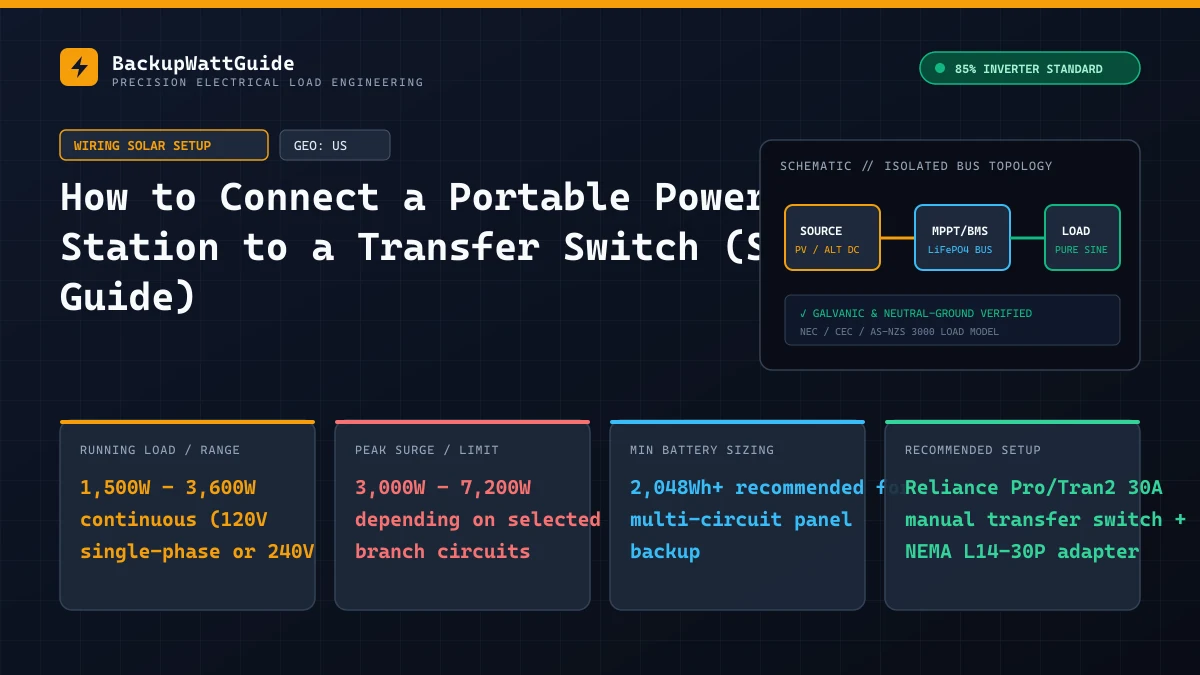
Running five extension cords through cracked basement windows and across dark hallways during a winter blackout is messy, trips family members, and leaves no way to power hardwired essentials like a natural gas furnace blower, a hardwired well pump, or kitchen overhead lighting. Connecting your portable power station to a manual transfer switch (such as a 6-circuit or 10-circuit Reliance Controls Pro/Tran2) lets you flip six switches next to your main breaker panel and energize key rooms in 30 seconds.
However, portable battery stations do not behave like loud open-frame gas generators. Battery inverters use solid-state ground-fault sensing, floating neutral architectures, and strict 120V single-phase vs. 240V split-phase limits. If you plug a power station into a generator inlet box using the wrong adapter or leave a bonding plug inserted, you will either trip the station immediately or create a dangerous overload on shared household neutral wires.
Why you must never use a male-to-male “suicide cord” to backfeed an outlet
Every storm season, DIY videos suggest building a double-male extension cord, turning off the main 200A house breaker, and plugging a portable power station directly into a garage wall outlet or 240V dryer socket.
Aside from violating NFPA 70 (National Electrical Code) Article 702 in the US, the Canadian Electrical Code (CEC), and AS/NZS 3000 in Australia, backfeeding a wall outlet with a battery power station destroys equipment for three concrete reasons:
- Instant H-Bus / Inverter Blowout on Grid Return: If someone forgets to flip the main breaker off (or flips it back on when street lights return), 200 amps of utility grid power collides out-of-phase with your power station’s MOSFET bridge. Unlike a spinning iron generator rotor that shears a mechanical key, a solid-state LiFePO4 inverter vaporizes its output transistors in microseconds—or latches a permanent E03 internal H-Bus over-voltage fault.
- Lethal Utility Transformer Step-Up: If your main breaker is left closed during an outage, your 120V/240V battery feeds backward into the neighborhood pole transformer, stepping your battery output up to 7,200V or 13,800V on downed street lines where utility crews are working.
- Exposed Live Prongs: The moment you press the AC button on a power station with a double-male cord attached, the bare brass blades on the far end carry 120V at up to 30 amps before they even touch the wall socket.
A UL 1008 listed manual transfer switch (or a code-approved mechanical Generator Interlock Kit installed on the main panel cover) physically blocks the utility circuit and the backup inlet from closing at the same time.
Understanding the 2 types of manual transfer switches (Neutral Switched vs. Solid Neutral)
Before plugging a Bluetti, EcoFlow, Anker SOLIX, or Jackery into a transfer switch inlet, you need to know how that switch handles the White Neutral Wire. Almost every electrical bug between portable power stations and home panels comes down to this distinction:
| Transfer Switch Type | Common Models | How Neutral & Ground Work | Compatible Power Station Types |
|---|---|---|---|
| 1. Solid Neutral (Non-Separately Derived System) (95% of residential switches) | Reliance Controls Pro/Tran2 (306C, 310C), Generac HomeLink, Panel Interlock Kits | Only switches the Black Hot wire between LINE and GEN. The White Neutral and Green Ground wires stay permanently bonded together inside your main house panel. | Floating-Neutral Power Stations (EcoFlow DELTA 2/Max/Pro, Bluetti AC180/AC200L/AC300, Anker SOLIX C1000/F2000). Do NOT use a bonding plug! |
| 2. Switched Neutral (2-Pole / 3-Pole Separately Derived System) | Reliance Controls X-Series (XRK), Generac 6852 (Modified), Canadian CSA-mandated subpanels | Switches both the Black Hot AND White Neutral wires away from the main house panel when flipped to GEN. | Requires a Bonded-Neutral Source (or a floating-neutral power station with a Neutral-Ground bonding adapter installed on the station side). |
Why your furnace works on a transfer switch without a bonding plug
If you ever tried running your home heating furnace with an extension cord plugged straight into a portable power station, you probably discovered the furnace blower started for three seconds and shut down with a flame-sensor fault code because the power station has a floating neutral.
When you wire that exact same floating-neutral power station into a standard Reliance Controls Pro/Tran2 transfer switch, the furnace runs perfectly without any bonding plug. Why? Because the transfer switch connects your power station’s neutral wire directly to your main household breaker panel’s neutral bus bar, which is already permanently bonded to your home’s copper grounding rods. Your power station automatically borrows your house’s Neutral-Ground bond! (For direct plug-in setups without a transfer switch, see our dedicated guide on powering a natural gas furnace blower fan.)
Matching your power station outlet to a 30A transfer switch inlet (120V vs. 240V)
Most residential 6-circuit and 10-circuit manual transfer switches use a 4-prong NEMA L14-30P twist-lock male inlet rated for 30 Amps at 120V/240V split-phase. Those four prongs represent:
- X (Hot Leg 1): 120V to Neutral
- Y (Hot Leg 2): 120V to Neutral (180 degrees out of phase with Leg 1 on a true 240V generator, giving 240V between X and Y)
- W (White Neutral): Return path
- G (Green Equipment Ground): Chassis safety ground
Portable power stations fall into three outlet categories. Match your station to the correct cord configuration below:
Setup A: True 240V Split-Phase Power Stations (Plug & Play)
- Models: Anker SOLIX F3800, EcoFlow DELTA Pro Ultra, Dual EcoFlow DELTA Pro with Double Voltage Hub, Dual Bluetti AC300/AC500 with Fusion Box.
- Outlet on Station: Native 4-prong NEMA L14-30R (or 50A NEMA 14-50R).
- How to Connect: Run a standard 10 AWG 4-wire L14-30 generator cord directly from the power station to the transfer switch inlet. Both Hot Leg 1 (Circuits A, B, C) and Hot Leg 2 (Circuits D, E, F) receive true 120V/240V out-of-phase power, meaning you can run 240V double-pole well pumps alongside 120V fridge and lighting circuits safely.
Setup B: 120V 30-Amp RV-Outlet Power Stations (Bridged 120V Mode)
- Models: EcoFlow DELTA Pro (single unit), Bluetti AC200Max / AC200L / AC300 (single unit), Anker SOLIX F2000 / F2600, Jackery Explorer 2000 Plus.
- Outlet on Station: 3-prong NEMA TT-30R (120V, 30A RV socket) or 3-prong NEMA L5-30R twist-lock.
- How to Connect: Use a UL-listed NEMA TT-30P to L14-30R generator adapter connected to your 10 AWG L14-30 cord. Inside this adapter, the single 120V Hot pin from the power station splits and feeds both the X and Y hot legs of the transfer switch simultaneously.
Setup C: Mid-Size 120V 15A/20A Power Stations (1,000W to 1,800W Class)
- Models: EcoFlow DELTA 2 / DELTA 2 Max, Bluetti AC180, Anker SOLIX C1000, Jackery 1000 v2.
- Outlet on Station: Standard household 3-prong NEMA 5-15R / 5-20R (120V, 15A–20A).
- How to Connect: Use a heavy-duty NEMA 5-15P to L14-30R bridging adapter (wired internally to tie X and Y hot blades together). Because the outlet on your station is limited to 15A (1,800W), you must manage which transfer switch circuits you flip to
GENat the same time.
The critical danger of bridging X and Y hot legs: Multi-Wire Branch Circuits (MWBC)
If you use Setup B or Setup C (feeding a 4-prong L14-30 transfer switch from a 120V-only power station using an adapter that bridges Hot Leg X and Hot Leg Y together), you must obey two mandatory electrical rules:
- Zero 240V Loads: Because Leg X and Leg Y are now fed by the exact same 120V phase, the voltage difference between X and Y is 0 Volts (not 240 Volts). Any 240V double-pole circuit on your transfer switch will simply stay dead—flip all 2-pole breakers to
OFForLINE. - Check for Multi-Wire Branch Circuits (Shared Neutrals): In many homes built before 2011, electricians ran a single 3-wire cable (
Red Hot,Black Hot,White Shared Neutral) to the kitchen or garage to power two separate 15A or 20A circuit breakers using one shared neutral wire.- On normal 240V grid power: Red Hot and Black Hot are on opposite phases. If Red pulls 12A and Black pulls 12A, the currents cancel out and the shared White Neutral carries 0 Amps.
- On a 120V Bridged Power Station Adapter: Red Hot and Black Hot are now on the same phase. If you put both halves of an MWBC onto your transfer switch and pull 12A on Red and 12A on Black (using a 30A 3,600W 120V EcoFlow DELTA Pro), the currents add together, sending 24 Amps down a 14 AWG White Neutral wire rated for only 15 Amps—without tripping either 15A breaker!
How to stay 100% safe: If your power station outputs 15A or less (1,800W max, like a Bluetti AC180 or EcoFlow DELTA 2), the inverter itself physically cannot output more than 15A total across all circuits combined, making it impossible to overload a 15A/20A neutral wire. If you use a 30A 120V station (3,600W) with a bridging adapter, verify with your electrician that none of the circuits wired into your transfer switch share a Multi-Wire Branch Circuit neutral, or only flip one side of any MWBC pair to GEN at a time. Refer to Reliance Controls Pro/Tran2 installation documentation for official circuit mapping rules.
Step-by-step procedure to switch your home over to battery power
Follow this exact sequence during an outage so inrush surges from refrigerators and sump pumps do not trip your power station into an immediate E01 overload:
- Leave all transfer switch rockers in the
LINE(orOFF) position first. Never plug in or boot up a portable power station while six household circuits are already switched toGENunder load. - Unplug the power station’s AC wall-charging cord and remove any neutral-ground bonding plugs. Your power station must be completely disconnected from any household wall outlets before you connect its output to the transfer switch inlet. Leaving the station plugged into a wall outlet while connected to a transfer switch creates a ground-neutral loop—see our troubleshooting guide on why your power station trips GFCI outlets when charging.
- Connect the L14-30 cord between the transfer switch inlet box and your power station. Twist the L14-30 plugs clockwise until locked.
- Power on the station and enable the 120V/240V AC Inverter button. Wait 5 seconds for the LCD screen to show stable voltage (
120Vor240V,60Hz) and0Wload. - Disable “ECO / AC Auto-Shutoff” mode in the mobile app. Just like running a standalone pump, if your house load drops below 20W at 3:00 AM, ECO mode will turn off your entire transfer panel.
- Flip transfer switch circuits from
LINEtoGENone at a time, starting with the heaviest motor load.- Flip Circuit 1 (Refrigerator or Sump Pump) to
GENfirst. Wait 10 seconds for the compressor or sump pump startup surge to settle down to running wattage. - Flip Circuit 2 (Furnace Blower) to
GENsecond and wait for the blower motor to ramp up. - Flip Circuits 3–6 (LED lighting, Wi-Fi router, bedroom outlets) to
GENlast.
- Flip Circuit 1 (Refrigerator or Sump Pump) to
Calculating multi-circuit transfer switch runtime
When you energize four to six rooms through a transfer switch, small “phantom loads” (microwave clocks, smart switches, GFCI indicator LEDs, doorbell transformers, and your station’s 20W inverter idle draw) add up quickly. A typical 6-circuit transfer switch carries a 60W to 90W baseline load even when the fridge and furnace are cycling off.
Use the calculator below to model your combined average continuous wattage across your selected transfer switch circuits against your battery bank’s Watt-hour capacity:
Real-World Battery Runtime Calculator (85% Inverter Efficiency)
Sample 6-circuit load budget on a 2,048Wh power station (1,800W–2,400W inverter)
| Transfer Switch Circuit | Connected Appliance | Peak Surge Watts | Average Hourly Draw (Cycled) | Notes for Load Management |
|---|---|---|---|---|
| Circuit 1 (15A) | Kitchen Refrigerator (Energy Star) | 1,200W | ~55 Wh/hr | Runs ~25 mins/hr at 130W once cold. |
| Circuit 2 (15A) | Gas Furnace Blower (ECM Motor) | 900W | ~120 Wh/hr | Runs ~20 mins/hr at 360W in winter. |
| Circuit 3 (20A) | Basement Sump Pump (1/3 HP) | 1,800W | ~35 Wh/hr | Cycles 12x/hr in moderate storm. |
| Circuit 4 (15A) | Home Office / Fiber ONT & Wi-Fi Router | 35W | ~30 Wh/hr | Continuous 24/7 draw. |
| Circuit 5 (15A) | Master Bedroom + Bath LED Lights | 60W | ~20 Wh/hr | Avoid using 1,500W hair dryers on GEN! |
| Circuit 6 (20A) | Kitchen Counter Outlets (Microwave/Kettle) | 1,600W | Manual Use Only | Flip Circuit 1 & 3 to OFF temporarily while running microwave. |
With Circuits 1 through 5 active, your average hourly draw sits around 260W + 20W inverter idle = 280W. On a 2,048Wh LiFePO4 battery station (yielding 1,740Wh after 85% inverter efficiency), you get 6.2 hours of whole-essentials backup on the internal battery alone—or 12.5 hours when paired with one expansion battery (4,096Wh total).
# Frequently Asked Questions
Can I connect a 120V-only portable power station (like an EcoFlow DELTA 2 or Bluetti AC180) to a 4-prong L14-30 transfer switch inlet?
Yes, by using a NEMA 5-15P (or TT-30P) to L14-30R bridging adapter that ties the X and Y hot blades of the transfer switch together into a single 120V phase. However, you must never flip on any 240V double-pole breakers (such as a well pump or electric dryer) and you must never use a bridging adapter on a panel containing Multi-Wire Branch Circuits (MWBCs) sharing a single neutral wire, or you can overload the neutral conductor.
Why does my gas furnace or portable power station throw an error when plugged into a Reliance Pro/Tran2 transfer switch?
Standard 6-circuit and 10-circuit manual transfer switches (like the Reliance Controls Pro/Tran2) only switch the black Hot wire of each circuit; the white Neutral and green Ground wires stay permanently connected to your main household breaker panel. Because your main breaker panel already bonds Neutral to Ground, a portable power station with a floating neutral inherits the house bond automatically—meaning you must remove any neutral-ground bonding plugs before connecting to the inlet box.
Can I charge my portable power station from a wall outlet in my house while it is plugged into the transfer switch?
Only if the wall outlet you are charging from is on a circuit that remains on LINE (utility grid) power and is NOT one of the circuits wired through the transfer switch, AND your power station does not trip due to a neutral-ground loop through the shared panel bus. In practice, connecting both the AC input cord and the AC output cord of a non-isolated power station to the same home electrical panel creates a parallel neutral loop that often trips GFCI breakers or triggers an internal H-Bus E03 fault.
Lead Technical Electrical Editor
Peer-ReviewedPower Systems Analyst & Backup Power Specialist
All technical guides and electrical sizing benchmarks are calculated using standard Nameplate Full Load Amps (FLA), Locked Rotor Amps (LRA) surge models, and an empirically verified 85% Inverter Power Factor & Conversion Efficiency model.